
This is a web page version of a report from Living Streets, which is also published as a pdf document. This version has been adapted to focus on providing accessibility for people who want to enlarge the text or to use a screen reader.
The key information below is taken from the document cover pages:
Document title: Inclusive design at continuous footways: Appendices 2-4
Document date & version: October 2023, Version 1.3.2
Publishing organisation: Living Streets
Author/research lead: Robert Weetman
This appendix provides some additional details on ramp design at continuous footways.
Table 1 shows the varying ramp arrangements at the research detailed-study sites.
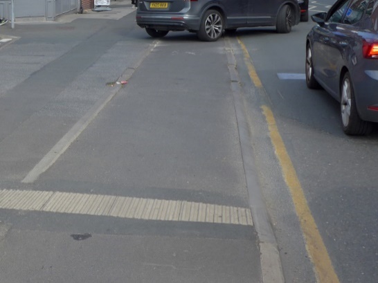
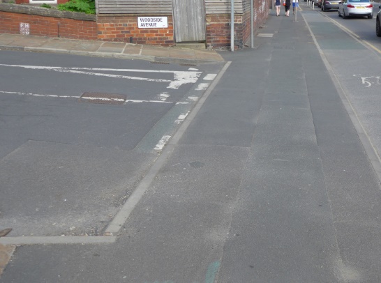
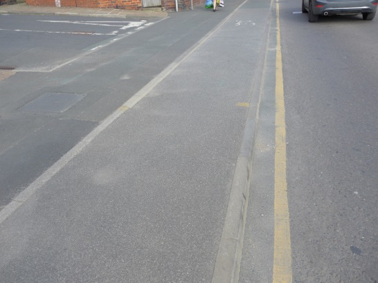
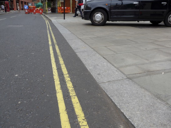
In this webpage version of the document, Table 1 has been converted into ordinary text and images, which follow here. For each site there are two photographs, the first showing the ramp at the side road carriageway, and the second showing the ramp at the main road carriageway.
Cardiff: Glamorgan St
Edinburgh: Simpson Loan (flush / minimal)


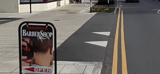
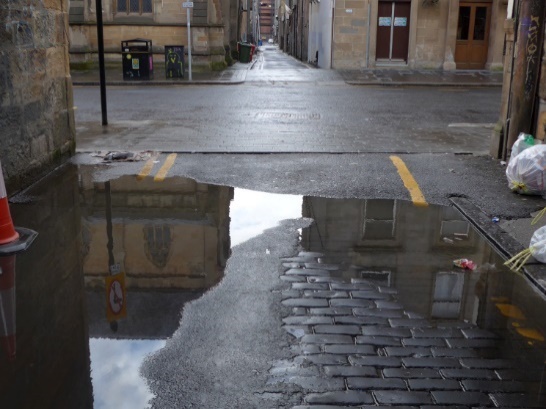
Glasgow: Sauchiehall Lane (high / steep)

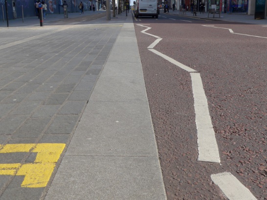
Glasgow: Scott Street (flush)

Glasgow: Drury Street (flush)

Leeds: Haddon Road (flush)

Leeds: Woodside Avenue (flush)
London: Lansdowne Terrace (flush / gentle)


London: Wilfred Street (flush / gentle)

London: Alderney Road (gentle)

Note that other factors, beyond actual ramp design, also affect how easily a ramp is driven over. These factors include the degree of crossfall on the footway and on the carriageway, and any incline along the side road (as visible at Woodside Avenue and Scott Street in the images above).
The project determined that “exit constructions” – which create a continuous footway – are much more common on Dutch streets than elsewhere.
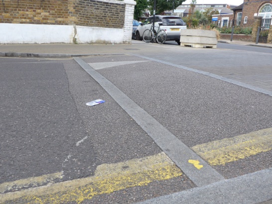
The presence of an “exit” in the Netherlands is defined (legally / partly) by the inclusion of entrance kerbs (“inritbanden”) – which create a ramp at either side of the section of footway which can be driven over. The images in Figure 1 show three Dutch examples at junctions between public streets and one example at the entrance to a petrol station.


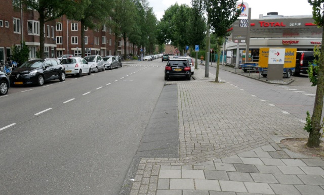

These entrance kerbs are arranged in a straight line as a continuation of the ordinary kerbs on the main carriageway, without any indentation which could suggest the beginning of a side road. In addition to specifying the use of entrance kerbs as a defining feature of an “exit”, Dutch guidance also specifies that there must not be any kerb corners which might imply the beginning of a section of carriageway.
The research determined that in contrast many British continuous footway structures have ramps constructed from asphalt, visually suggesting the beginning of the side road carriageway.
A simple search of the internet provides specifications for a variety of “inritbanden” for use within the Netherlands to construct exits and entrances (“uitritconstructie”). These are for a variety of uses, including at private entrances and on exit constructions over public streets. Table 2 provides details.
| Website or company | Height of ramp (mm) | Length of ramp climbed (mm) | Reference | Gradient |
|---|---|---|---|---|
| Betondingen | 100 | 450 | https://www.betondingen.nl/inritband-middenstuk-vl.html | 22% |
| Struyk Verwo Infra | 115 | 400 | https://www.struykverwoinfra.nl/productselector/banden/trottoirbanden-13-15/inritbanden-13-15/inritbanden-45x18x75-vb.html | 29% |
| Struyk Verwo Infra | 125 | 400 | https://www.struykverwoinfra.nl/productselector/banden/trottoirbanden-13-15/inritbanden-13-15/inritbanden-45x18x100-vb.html | 31% |
| Struyk Verwo Infra | 125 | 600 | https://www.struykverwoinfra.nl/productselector/banden/trottoirbanden-18-20/inritbanden-18-20/inritbanden-65x25x50-hd.html | 21% |
| Struyk Verwo Infra | 124 | 460 | https://www.struykverwoinfra.nl/productselector/banden/trottoirbanden-18-20/inritbanden-18-20/inritbanden-50x20x75-vl.html | 27% |
| Struyk Verwo Infra | 120 | 770 | https://www.struykverwoinfra.nl/productselector/banden/trottoirbanden-18-20/inritbanden-18-20/inritbanden-80x18x50-vb.html | 16% |
| Struyk Verwo Infra | 125 | 400 | https://www.struykverwoinfra.nl/productselector/banden/trottoirbanden-18-20/inritbanden-18-20/inritbanden-50x16x50-hd.html | 31% |
| Giverbo | 125 | <450 | https://giverbo.s3.amazonaws.com/artikel/2/16660.jpg | >28% |
| Giverbo | 125 | <450 | https://giverbo.s3.amazonaws.com/artikel/2/16671.jpg | >28% |
| Giverbo | 125 | 575 | https://giverbo.s3.amazonaws.com/artikel/2/16684.jpg | 22% |
| Giverbo | 125 | 720 | https://giverbo.s3.amazonaws.com/artikel/2/16696.jpg | 17% |
In order to gain a rough sense of how these are used in the Netherlands our research team spoke to a Dutch urban designer/transport planner via social media channels. He said that as standard he used 45cm units (as in the first of the two Struyk Verwo Infra ramps listed above). He said that he used longer (gentler) ramps where there were a higher proportion of trucks driving over them, or where houses lacked proper foundations.
The ramp at Sauchiehall Lane in Glasgow is of a gradient and height more comparable to Dutch designs. This ramp design stood out as quite different to other UK sites - with the exception of similar designs found at around 10-20 other minor lanes elsewhere near Glasgow city centre (including at other junctions of Sauchiehall Lane).
We took approximate measurements of this ramp (there is no ramp between the actual lane surface and the footway, although the surface here is of poor quality). The ramp is 450mm long (in the direction climbed which is equivalent to 441mm horizontally), and the slope climbs around 100mm, providing a gradient of around 22%.
| Height of ramp (mm) | Length of ramp (mm) | Gradient | |
|---|---|---|---|
| Sauchiehall Lane ramp | 100 (±10) | 441 (±12) horizontal | 22.5% (±3%) |
Additional images of the ramp at the Sauchiehall Lane site are shown in Figure 2


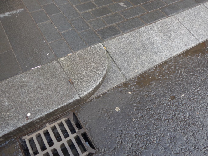

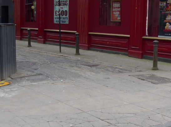
Local details mean that the height of the ramp varies a little at the other similarly constructed Glasgow designs. For example, at the junction of Anchor Lane with West George Street the kerbs sit higher compared to the surface of the carriageway, and higher at one end of the ramp than the other, meaning the ramp height varies from around 100-120mm in comparison to the carriageway.
The company Charcon introduced a “Dutch entrance kerb” into its range around two years ago, specifically to cater for the construction of continuous footways at side roads in Britain. These have already been used to construct continuous footway structures, for example in Coventry and Leeds.
Charcon have since also provided very similar custom made “driveway entrance kerb” units for a number of local authorities, who wanted to use these to create better quality level footways at footway crossovers.
The company Hardscape can be seen to be advertising a selection of “crossover kerb” units for use in the UK, referenced also as “inritbanden” on its website. These appear to be manufactured in the Netherlands and to have more standard Dutch dimensions.
Specifications of Charcon’s units, and several of the Hardscape units (more are advertised), are summarised in Table 4.
| Company | Height of ramp (mm) | Length of ramp climbed (mm) | Reference / link | Gradient |
|---|---|---|---|---|
| Charcon | 65 | 750 | “Dutch entrance kerb” https://www.aggregate.com/products-and-services/commercial-landscaping/kerbs/dutch-kerb |
9% |
| Charcon | 75 | 500 | Driveway access kerb (Aberdeenshire) | 15% |
| Charcon | 50 | 300 | Driveway access kerb (BCP) | 17% |
| Hardscape | 70 | 355 | https://hardscape.co.uk/select/materials/middle-crossover-kerb-400x200-130-entry-kerb-sloped/ | 20% |
| Hardscape | 120 | 250 | https://hardscape.co.uk/select/materials/middle-crossover-kerb-300x240-150-entry-kerb-sloped/ | 48% |
| Hardscape | 120 | 290 | https://hardscape.co.uk/select/materials/middle-crossover-kerb-450x200-125-entry-kerb-sloped/ | 41% |
| Hardscape | 75 | 290 | https://hardscape.co.uk/select/materials/middle-crossover-kerb-450x200-125-entry-kerb-sloped-vb/ | 26% |
The Charcon kerbs have a substantially lower ramp height (50-75mm) in comparison to what appear to be typical Dutch units (100-125mm), and a lower gradient (9-17% compared to 16-31%). We spoke to a representative from Charcon, who confirmed that their units were designed according to the specifications requested by their customers, and that (in theory) steeper/higher ramps could be manufactured.
In the main section of the report we propose that “real” continuous footways should only be installed in limited circumstances. This appendix summarises our recommendations on the applicable limits.
While many of the limitations described here are in relation to traffic speed or volume we have not provided absolute figures. These are difficult to determine, and in any case a wider range of factors mean that numerical limits are of limited use.
We consider that in most cases a study of a proposed site can provide objective evidence as to whether the conditions detailed below can be met.
There must be sufficient local constraints (i.e. created by the structure itself) on vehicle speed, path and movement as follows:
There must be a sufficiently steep and high ramp to slow most motor vehicles to around a walking pace.
There must be constraints on the path on which vehicles can be driven, requiring that they turn so tightly on entering that - for those not sufficiently slowed by ramps - they are only driven at a walking pace.
There must be constraints on the size of the area of footway which can be driven over such that vehicles cannot simultaneously be driven across this area in two directions.
There must be wider limitations on conditions, or installation only where these conditions already exist, as follows:
There must be a sufficiently low speed environment in the side road (or equivalent) so that it would feel reasonable for drivers to slow significantly before entering that side road, even in the absence of a continuous footway.
There must be a sufficiently low speed environment in the side road (or equivalent) so that pedestrians find it trivial to judge whether they can cross ahead of an exiting vehicle, even in the absence of a continuous footway.
There must be a sufficiently low speed environment on the main carriageway so that drivers are comfortable to slow or to stop while still blocking other vehicles on this carriageway (i.e. before turning onto the continuous footway).
There must be conditions on the main carriageway which mean that drivers turning right into the side road across oncoming traffic can stop part way through that manoeuvre (while still on the main carriageway) without fear for their safety.
There must be an environment in which it is rare that vehicles queue to exit the side road (or equivalent).
This appendix records some technical challenges involved in the analysis of continuous footways. We consider that this may be of interest to others involved in similar research.
At the beginning of the project it was recognised that it is inherently difficult to study how people are excluded from use of the streets. Many of the reasons for this are obvious:
It is difficult to study the challenges facing people who have already opted not to use new infrastructure, because they can’t be seen struggling to use it.
Fear is itself a barrier and the fear generated by controversy about new infrastructure can become a barrier of its own.
Small additional issues caused by new infrastructure can lead to the complete exclusion of those already on the brink of being excluded by existing conditions. Such problems are mostly a result of existing conditions, but it is the provision of the new infrastructure which tips the balance.
Changes to streets can cause controversy and anger even when their overall effects are positive.
It can be difficult to separate genuine accounts of specific issues caused by the installation of new infrastructure from objections made by those opposed to changes because they disagree with a scheme’s overall objectives (e.g. where a scheme is intended to encourage cycling).
Issues of inclusion and exclusion can be specific to individual people, or to very small groups of people.
The second set of issues are caused by difficulties defining what is and is not a continuous footway.
A decision has to be taken on what to include in a study of continuous footways. This choice is likely to have a profound effect on any analysis which tries to draw conclusions over whether continuous footways provide pedestrian priority.
Any findings are difficult to communicate because those interested in the results of a study may have different ideas about what has been studied.
There are also issues which arise when trying to analyse or classify interactions between pedestrians and vehicles.
What is and is not an interaction is extremely hard to classify in the real world. Many actual interactions sit on a borderline between being interactions and not being interactions. These borderline interactions tend to have a particular character of their own. Thus, decisions over what to count as an interaction might have a profound effect on any attempt to summarise the percentage of interactions which have a particular character.
Vehicle speed is a significant factor in interaction character and outcome. Interactions between pedestrians and vehicles (and their drivers) at side road ends take place where drivers are already slowing. It is often impossible to distinguish from observations whether a vehicle is being slowed because of the presence of a pedestrian or for practical reasons to do with negotiating a corner or other vehicles.
Higher vehicle approach speeds can create a situation where there is some level of interaction between pedestrians and vehicles at a considerable distance from the actual end of a side road.
There is no practical method (in a study of this size and character) to accurately record the way in which vehicle speeds vary as they are driven through a side road junction, particularly given that such information needs to be correlated against the real-world physical detail at a site.
Most pedestrians appear very skilled at crossing the end of side roads, and they are rarely seen to show stereotypical road-crossing behaviours (i.e. stopping, looking for traffic, then crossing when safe). Even in dangerous locations they may only glance briefly toward (potential) oncoming vehicles. In early trial observations we noted that many appeared to use a developed understanding of driving behaviour in assessing their safety (for example understanding that vehicles travelling in one direction block entry to a side road to those travelling in the other direction, removing the need to check for these).
Other than at very quiet sites, an additional problem arises from the fact that interactions can be interrelated – meaning that a full analysis must qualify the effect of these interactions on each another.
This is directly relevant when trying to analyse give-way behaviours.
In more detail, at busier sites:
One vehicle can be involved in many pedestrian interactions.
One pedestrian can be involved in interactions with more than one vehicle.
Where vehicles are queuing pedestrians may cross between these. Drivers typically don’t “give way” as such, but instead wait to start moving.
Drivers who give way to one pedestrian (perhaps as above, when queuing) may then find other pedestrians cross because they are stationary. This isn’t “giving way” but simply waiting to start moving.
Where there are more steady flows of pedestrians drivers may be reacting to a group of unrelated pedestrians, rather than to individual pedestrians.
Some additional issues relate to the flexible manner in which most people drive. For example:
It is clear that on exiting many ordinary side roads most drivers slow but don’t stop, finding a gap in traffic while their vehicle continues to move. We saw drivers modify this behaviour in order to allow pedestrians to cross (by slowing down more or sooner), but there was no objective way in which to determine when this did or did not occur.
From brief informal study of behaviours at more standard side road junctions it appears that drivers who do stop to wait for a gap in traffic often do not do so in the locations officially marked (with painted lines on the carriageway).
At some of the sites we saw drivers being forced to give-way to pedestrians who we thought had accidentally walked in front of the vehicle. We observed drivers respond quickly to such circumstances by stopping or slowing. Such interactions often appeared, on the surface, to be identical to give-way behaviour in which the driver looks ahead and anticipates the interaction, slowing or stopping to invite the pedestrian to cross. Any full analysis of behaviours should distinguish these two quite different situations.
Confident pedestrians may sometimes pretend that they haven’t seen an approaching vehicle, to force the driver to give way to them. An observer can’t tell the difference between a pedestrian who hasn’t seen an approaching vehicle and one who is pretending not to have seen it. A full analysis of behaviours would need to take account of the difference, but also the fact that a good design might increase the number of pedestrians behaving in this way.
Drivers and pedestrians sometimes communicate directly with one another with nods or smiles or other small gestures – all of which are difficult for an observer to detect.
Options available to pedestrians are very varied, and are not restricted to proceeding or giving way. For example pedestrians in our study could be seen sometimes to anticipate risks by crossing a few metres into the end of the side road. Such behaviours are difficult to classify.
Very subtle driver behaviour can convey a sense of invitation, impatience, assertiveness, or aggression – or politeness, patience, and invitation. Such behaviour can be difficult for observers to detect, and interpretation of such behaviours is inherently subjective.